
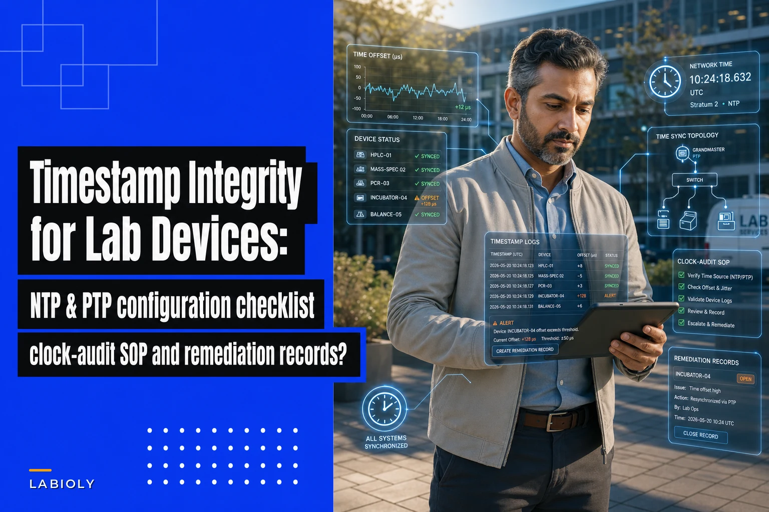

Your mass spectrometer logs a sample analysis at 14:23:47. The LIMS records sample receipt at 14:24:12. The audit trail shows the analysis happened before the sample arrived.
This isn't science fiction—it's what happens when lab devices drift out of sync. And unlike most operational problems that just create inefficiency, timestamp integrity issues surface months later during audits, at the worst possible time.
The real mess starts when you realize your PCR cycler has been running 3 minutes fast for six months. Every temperature log, every cycle completion, every QC record now needs verification against a clock that nobody thought to check. The remediation paperwork alone takes weeks.
Why lab clocks drift (and nobody notices until an audit)
Lab instruments don't randomly lose time. Drift patterns are pretty predictable once you understand how devices connect to your network and which time protocols they support.
Standalone analyzers running embedded Windows often rely on their internal CMOS battery for timekeeping. When that battery weakens after 3–4 years, the clock starts drifting backward by seconds per day. You won't notice until the drift accumulates to minutes and someone spots impossible timestamps in the audit trail.
Network-connected instruments face different problems. Your HPLC might sync through NTP, but if it's configured to pull from pool.ntp.org through a corporate firewall, packet delays create jitter. The instrument thinks it's synchronized, but timestamps vary by 100–500 milliseconds between runs. For kinetic assays or reaction monitoring, that variance breaks your data integrity.
The worst scenario involves instruments behind air-gapped networks. These devices never sync automatically. A sequencer in a BSL-3 facility might go months between manual clock adjustments, and by the time someone catches the drift, hundreds of genomic runs carry incorrect timestamps that cascade through downstream analysis.
Temperature-controlled equipment adds another layer. Incubators and freezers often run simplified real-time clocks that drift faster in extreme conditions. A -80°C freezer's internal clock might lose 2–3 seconds daily just from electronics operating outside normal temperature ranges. After a year, that's a 15-minute discrepancy that makes temperature excursion logs essentially useless.
The cascade effect of timestamp problems
Bad timestamps don't stay isolated. They contaminate every process they touch.
Eliminate lab bottlenecks and errors.
Labioly helps you monitor, manage, and report lab activities efficiently and compliantly.
- Real-time sample tracking
- Inventory and supply alerts
- Staff workflow coordination
No credit card required
Consider a stability study where samples move between instruments. The prep balance logs weighing at 09:00. The dissolution tester shows testing started at 08:57. The UV-Vis records analysis at 09:03. That three-minute backward jump makes the entire study questionable. Did someone falsify records? Did the test actually run out of sequence? The FDA won't care that it was just clock drift—they'll cite you for data integrity violations.
Sample chain-of-custody becomes impossible to verify. Your automated QC reporting pipelines start generating reports with negative processing times. The accessioning system shows samples analyzed before collection. Electronic signatures lose their legal weight when the signing timestamp predates document creation.
Environmental monitoring systems suffer particularly badly. When your particle counter runs 8 minutes fast and your air handler runs 5 minutes slow, correlating contamination events with HVAC cycles becomes guesswork. You know something happened around 14:30, but was that real time, particle counter time, or HVAC time? The investigation drags on for weeks just trying to reconstruct the actual sequence of events.
Integration failures multiply the damage. Modern labs running instrument data capture systems expect tight precision for data correlation. When your qPCR machine timestamps fluorescence readings with 2-second precision while your liquid handler logs aspirations with millisecond precision, the integration layer can't properly sequence events. Automated workflows break. Manual intervention increases. Error rates climb.
Building your NTP/PTP configuration checklist
Getting timestamp integrity right means knowing which protocol fits each device category. Not every instrument needs microsecond precision, but every instrument needs synchronization appropriate for its role.
Primary time sources (Stratum 1)
Your lab needs at least one authoritative time source. Options include:
-
GPS-disciplined NTP server (±50 nanoseconds)
-
Dedicated PTP grandmaster clock (±100 nanoseconds)
-
Local atomic clock reference (±10 nanoseconds)
GPS-based servers work well for most labs. Mount the antenna with clear sky view, run coax to the server location, configure as stratum 1. Hardware typically runs $2,000–4,000 and handles 10,000+ NTP requests per second without breaking a sweat.
Critical path instruments
Devices directly involved in time-sensitive measurements need PTP (Precision Time Protocol):
-
High-speed liquid handlers (±1 microsecond)
-
Flow cytometers with sorting (±10 microseconds)
-
Mass spectrometers with SWATH acquisition (±100 microseconds)
-
Automated microscopes with time-lapse (±1 millisecond)
Configure these instruments as PTP slaves to your grandmaster. Use PTP-aware network switches to maintain precision through the network path. Enable hardware timestamping where supported.
Standard analytical instruments
Most analytical equipment is fine with standard NTP:
-
Spectrophotometers (±100 milliseconds)
-
pH meters (±1 second)
-
Balances (±1 second)
-
Centrifuges (±5 seconds)
Point these devices to your internal NTP server, not external pools. Configure polling intervals based on required precision—every 64 seconds for critical instruments, every 1024 seconds for basic equipment.
Embedded and standalone devices
Older instruments without network connectivity need special handling:
-
Manual sync during PM cycles
-
External NTP client devices for serial/USB connection
-
Scheduled technician rounds for clock verification
-
Documentation of maximum acceptable drift between syncs
For a thermal cycler drifting 3 seconds monthly, quarterly manual sync during PM works fine. For a liquid scintillation counter processing time-decay studies, you probably need weekly verification.
Here's a quick visual of the configuration workflow.
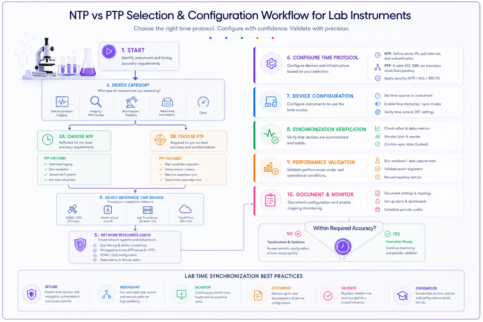
Use this as a reference when assigning protocols and setting up verification steps.
Clock audit SOP that catches drift before auditors do
Regular clock audits prevent nasty surprises during regulatory inspections. Here's an SOP that actually holds up in practice.
Monthly spot checks
Pick 10% of instruments randomly each month. For a 60-instrument lab, that's 6 devices monthly, which ensures full coverage every quarter.
Document these fields:
-
Instrument ID and location
-
Reference time source
-
Instrument displayed time
-
Observed offset (seconds)
-
Drift since last check (seconds/day)
-
Pass/fail against tolerance
Tolerance thresholds depend on instrument criticality:
| Instrument Class | Tolerance |
|---|---|
| Critical path | ±1 second |
| Analytical | ±30 seconds |
| Support equipment | ±5 minutes |
Quarterly systematic verification
Every three months, audit all network-connected instruments simultaneously. Use automated scripts that:
-
Query NTP/PTP synchronization status
-
Calculate offset from reference
-
Check last successful sync time
-
Verify sync source validity
-
Generate exception reports
This catches configuration problems like instruments syncing to decommissioned servers or firewall rules silently blocking NTP traffic.
Annual configuration review
Once a year, verify the entire time infrastructure:
-
GPS antenna signal strength and position
-
NTP server stratum accuracy
-
PTP grandmaster holdover performance
-
Network path symmetry for PTP
-
Backup time source availability
-
Documentation currency
Include failover testing. Disconnect the GPS antenna and verify instruments fall back to secondary sources. Simulate network partitions and check that isolated instruments maintain acceptable accuracy.
Pre-audit preparation
Six weeks before any regulatory audit:
-
Run comprehensive clock verification on all instruments
-
Generate drift trend reports for the past year
-
Identify any instruments exceeding tolerance
-
Complete remediation before auditors arrive
-
Prepare evidence packages showing continuous monitoring
The evidence package should include monthly spot check records, quarterly verification reports, remediation documentation, and trend graphs showing timestamp stability over time.
Finding out-of-sync devices before they corrupt data
Manual clock checking wastes technician time and misses gradual drift. Monitoring that catches problems automatically is a much better use of everyone's time.
Network-based detection
For NTP-synchronized devices, monitor these metrics:
-
Offset from reference (should be ±100ms)
-
Round-trip delay (should be <50ms on LAN)
-
Jitter between polls (should be <10ms)
-
Time since last successful sync (<2x poll interval)
Simple NTP monitoring check import subprocess import json def checkntpstatus(deviceip): cmd = f"ntpq -pn {deviceip}" result = subprocess.run(cmd, shell=True, capture_output=True, text=True) # Parse output for offset, delay, jitter # Flag if offset > 100ms or last sync > 3600 seconds # Log results to monitoring database
Set alerts for:
-
Offset exceeding threshold for instrument class
-
Sync failures lasting >2 polling intervals
-
Jitter indicating network problems
-
Stratum changes suggesting source issues
Application-level detection
Monitor timestamps in actual data:
-
Sample receipt before collection
-
Analysis completion before start
-
Negative duration calculations
-
Timestamp reversals in sequences
-
Gaps indicating clock adjustments
Your LIMS or data system should flag these automatically. When the pH meter reports readings from next Tuesday, something's wrong.
Physical verification patterns
-
Photograph display during each PM
-
Log timestamps in maintenance database
-
Calculate drift rate between checks
-
Project when tolerance will be exceeded
-
Schedule correction before hitting the threshold
A balance drifting 2 seconds daily needs adjustment every 15 days to stay within ±30 second tolerance. Schedule it for day 12 to keep a buffer.
Cross-instrument validation
-
Prep balance
10:15:32
-
Dissolution tester
10:18:45
-
HPLC injection
10:47:23
-
UV detection
10:51:17
The intervals should match your SOP timing. If dissolution shows 10:08:45—before weighing—you've found a sync problem.
Remediation scripts that fix issues fast
When you find timestamp problems, fix them systematically. Rushed corrections create new problems.
Immediate sync for networked devices
Windows instruments w32tm /resync /force # Linux instruments sudo chronyc makestep # Generic NTP sudo ntpdate -b ntp-server.lab.local
Document the correction:
-
Device ID
-
Original offset
-
Correction applied
-
New offset verified
-
Operator ID and timestamp
Gradual correction for small offsets
Adjust clock gradually over next hour sudo ntpdate -B ntp-server.lab.local # Or configure permanent slewing echo "tinker step 0" >> /etc/ntp.conf
This prevents negative timestamps in continuous monitoring.
Large offset remediation
-
Stop any running analyses
-
Document current offset with screenshots
-
Export recent data with original timestamps
-
Apply clock correction
-
Document new time with screenshots
-
Note correction in all affected batch records
-
Verify no data corruption occurred
-
Restart analyses with correct time
Don't correct large offsets during active sample processing. The timestamp discontinuity invalidates the entire run.
Manual device correction workflow
-
Print device configuration showing current time
-
Photograph display showing incorrect time
-
Access time settings (document menu path)
-
Enter correct time from reference source
-
Photograph display showing corrected time
-
Print updated configuration
-
Calculate drift rate since last correction
-
Update PM schedule if drift exceeds expected
Keep all documentation in the instrument logbook.
Audit-ready remediation records
Inspectors want evidence that you detected and corrected timestamp issues appropriately. Poor documentation leads to deeper investigation even when you did everything right.
Deviation documentation
Each timestamp deviation needs:
-
Discovery method (routine audit, data anomaly, etc.)
-
Affected instruments list
-
Time period of incorrect timestamps
-
Maximum observed offset
-
Root cause analysis
-
Impact assessment on data integrity
The impact assessment matters most. Show that you've identified all affected data and either demonstrated no quality impact or properly invalidated compromised results.
Corrective action records
Document fixes comprehensively:
-
Correction methodology (step, slew, manual)
-
Verification of successful correction
-
List of affected batch records
-
Data integrity evaluation results
-
Prevention measures implemented
Include before/after screenshots, NTP query outputs, and signed attestations from the technicians who performed corrections.
Trending and prevention
Build charts showing:
-
Drift rates by instrument over time
-
Correlation with maintenance events
-
Reduction in deviations after improvements
-
Network latency impact on sync quality
A six-month trend showing steady improvement demonstrates control. Scattered points with no pattern suggests a persistent underlying issue that hasn't been addressed.
Change control integration
Significant time infrastructure changes need change control:
-
Moving from NTP to PTP
-
Changing reference time source
-
Modifying network architecture
-
Updating synchronization intervals
-
Replacing grandmaster clocks
Document risk assessments, validation protocols, and implementation verification. Show that changes improved rather than disrupted timestamp integrity.
Preventing timestamp drift with operational discipline
The best clock audit finds nothing wrong because your preventive measures are actually working.
Start with infrastructure. Redundant time sources eliminate single points of failure. When your primary GPS-disciplined server fails, instruments automatically fall back to secondary sources—no drift, no deviation, no remediation paperwork.
Network segmentation helps. Put critical instruments on a dedicated VLAN with PTP-aware switches, restrict broadcast traffic that creates jitter, and monitor bandwidth utilization. Saturated networks delay NTP packets and increase offset uncertainty more than most people realize.
For standalone instruments, make clock verification part of every workflow. Before starting an HPLC sequence, verify the display time matches the lab clock. Takes about 5 seconds, prevents hours of remediation later. Build it into your SOPs as a required checkbox item.
Standardize on fewer time protocols rather than supporting everything. Pick NTP for standard equipment and PTP for high-precision needs. Mixing SNTP, NTP, and PTP on the same network segment creates synchronization inconsistencies that are genuinely annoying to troubleshoot.
Environmental factors matter too. Air handlers cycling on and off create temperature variations that affect crystal oscillators. Vibration from nearby equipment impacts timing stability. Position sensitive instruments away from these disturbances when possible.
Battery replacement schedules are easy to overlook. Every 3 years or so, regardless of drift measurements, replace CMOS batteries in critical instruments. A $5 battery prevents timestamp corruption that costs thousands to remediate—it's not even a close call.
Replace CMOS batteries every 3 years to avoid timestamp corruption.
Training is where a lot of labs fall short. Technicians need to understand that changing an instrument clock affects data integrity, and there should be a clear policy: no ad-hoc clock adjustments without documentation. Route all corrections through the quality system.
Making timestamp integrity operational
Perfect time synchronization across every lab device isn't realistic. But systematic monitoring, clear procedures, and solid documentation keep timestamp issues from becoming compliance disasters.
Labs that handle this well treat time synchronization like any other critical utility—monitored continuously, maintained proactively, documented thoroughly. They catch drift before it impacts data and fix problems before auditors arrive.
Timestamp integrity also connects to everything else in the lab. Sample tracking, instrument coordination, regulatory compliance—all of it depends on accurate timekeeping. When time synchronization is solid, automation and integration that would otherwise be unreliable actually work.
AI-powered operational software can centralize this kind of monitoring, tracking drift patterns across all instruments and alerting before tolerances are exceeded. Instead of manual spot checks and paper logs, you get real-time visibility into your entire time infrastructure. The same platform that manages instrument data capture can verify timestamp consistency, flag anomalies, and maintain the audit trails that regulators expect to see.
When timestamps work correctly, nobody notices. When they fail, everyone scrambles. Build the infrastructure and processes that keep time on your side.
Ready to upgrade your lab operations?
Join 500+ labs using Labioly to save time, reduce errors, and enhance productivity and compliance.